


There are several photos on this page that are
viewable size.
Please be patient while they load. Thank you.
(First Posted October 18, 2003)
This page consists
of a description of the fuel system installed in the most recent Seawinds to
come out of Bowes Aviation.
A review of the ISPA incident log,
just as a review of most aircraft incident logs, shows that a high percentage of
aviation incidents stem from fuel system problems and anomalies. For this
reason, SNA (the manufacturer of the Seawind and Seawind kits) has
understandably been outspoken about builders making any changes to the factory designed
Seawind fuel system. Please, any modification to the fuel system must be done
with a thorough review by the experts. Installation of the system shown here
must be done with close coordination and review by Bowes aviation.
Bowes
Aviation and the ISPA are providing this page not as a recommendation, but for
information only, and are not liable for it's use.
The ISPA
thanks Mike Bowes for the text on this page, and Tony Jurcan for the sketch.
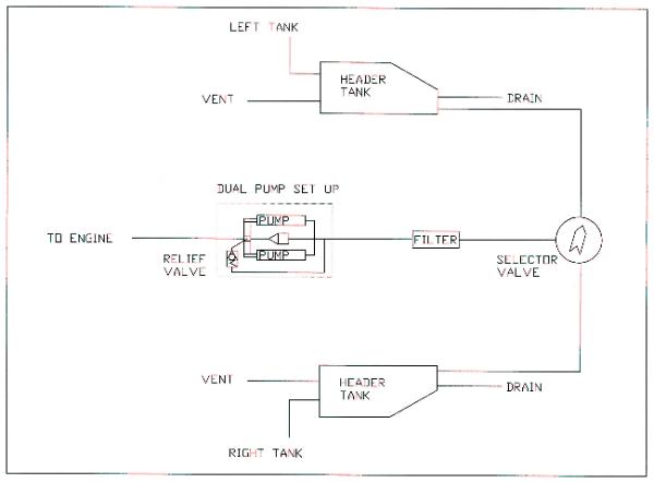
Diagram of the fuel system layout (provided by Tony Jurcan)
As many of you now know, N369JB has a dual header tank fuel system that feeds
into an Andair Left, Both, Right, Off fuel selector valve. Fuel then passes
through a stainless mesh fuel filter and then through an electric boost pump on
its way to the engine's mechanical pump.
In the beginning, I really didn't want to talk about my set-up or advertise
it in any way because it was unproven. Also, I had done the unspeakable. I had
MESSED WITH THE FUEL SYSTEM!
It's a different story now, though. The aircraft has been flying for a year
and a half and now has 178 hours on it. The system performs exactly as I had
envisioned it would, and gives the pilot total control over the fuel in the two
[main] tanks. Most Seawinds I have flown exhibit a tendency for one tank to feed
a little faster than the other. The reason this happens has been discussed at
length elsewhere and the subject can be debated all day long. It is not my
purpose to go into the reasons here and now. Simply accept that this is a fact
of life that shows up on longer flights and the standard "Both on" or
"Both off" system gives you no opportunity to balance fuel by
controlling which tank you're burning, as in most other aircraft.
My system remedies this perennial problem without forcing the pilot to resort
to the use of electric crossover fuel pumps. N369JB has the crossover system
installed, but I never need to use it. Simple is beautiful. Because the Andair
valve does not permit cross feeding from a high tank to a low tank, EVEN WHEN
SELECTED TO BOTH, my system requires no check valves. Check valves slightly
impede the gravity feed of fuel coming out of the tanks.
Those who attended the 2003 Fly-In were seemingly eager to learn all about
the system on N369JB which is being duplicated in the shop right now on the
Richard Wolf Seawind. For the first time, I was willing to talk about it and
explain the Bowes system features in detail. I would suggest this is not
something you can retrofit. Fuel lines must be installed prior to bonding down
the floors.
[The following provides] specific model numbers for the valve and the dual
fuel pump setup, company names, and phone numbers. I have gone back into
previous month's invoices to research this stuff and save all of you time and
possible aggravation. Enjoy and happy building.
Andair Ltd. Unit 15 The Tanneries, Havant, Hants PO9 1JB England
Phone: 011 023 9247 3945, 5 hours time difference, so call early in the
morning and you'll catch them before they leave work.
Valve model number FS25B4-B Fuel selector with 3 banjo fittings. Total cost
including shipping was 239 Pounds Sterling which converts to about $405.00 US,
and worth every penny.
Airflow Performance Inc. 111 Airflow Drive, Spartanburg, SC 29306
Phone: 864-576-4512
#8 Dual Fuel Pump Package part number 3090080 #8 Maintainable Fuel Filter
part number 1090161 Don Rivera will include all cushion clamps you need to mount
this stuff. Total bill including shipping and insurance to Florida was $713.00.
Mike and the mechanics, N369JB
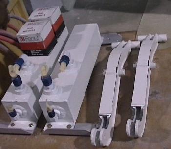
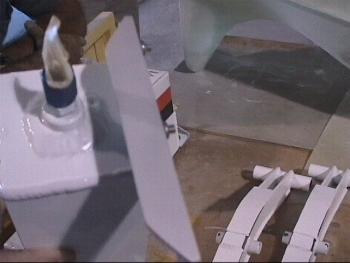
Dual header tanks shown above next to the
MLG retract arms for size comparison.
Dual header tanks are constructed from 3" by 3" square
aluminum tube and capped with 1" by 3" aluminum angle. All
material thickness is 1/8". The tanks incorporate only 4 fittings
each. Aluminum welding bosses are available from Spruce and Wicks.
You will need a pair of 1/8" NPT and a pair of 3/8" NPT fittings.
The small ones are centered in top and bottom of tank for static vent and
sediment drain, respectively. The pair of bigger ones create an
"Inflow" port and an "Outflow" port. That is, in from
the wing tank, and out to the Andair selector valve. Both of these bosses
should be welded onto the forward facing side of the tank, more or less side by
side, as space permits. On N369JB, the inflow occurs about 4" up from
the bottom of the tank. And here's the most important point. Picture
this. The outflow occurs about 5 inches up from the bottom of the tank.
Very important!
Compare this to your "stock" SNA tank where the outflow is right at
the bottom. There really is no sump to trap condensation and sediment
matter and contain it in the tank. My design assures a 4" to 5"
deep sump to trap these nasties and give you an opportunity to "sample them
out" onto the ground, during preflight. This system also eliminates
the large red check valves. These are no longer necessary, as the clever
design of the Andair valve does not allow for main tank cross-feeding [when
selected to "Off." It will however allow cross-over between the tanks
when in the "Both" position.] (See clarification below.)
Low points are bottoms of each header tank, which each have their own quick
drain in the main gear pockets on both left and right. I sump these drains
before and after each flight.
If desired, you could also "T" and create a sump drain in the main
line after the selector valve, headed up to the engine. Locate the quick drain
in a "pocket" facing aft, on the vertical part of the hull step, for
example. I opted not to do this, reasoning that high velocity fuel through this
tubing during operation periods of the electric boost pump (during engine start,
for takeoff and for landing) would eject moisture from this area, anyway.
We should note that fuel tank venting is done exactly as the SNA
manual shows you. Header tank venting is also as per manual instructions. The
header vents simply come together at a "T" and run on up to the SIDE
of the tail. Sediment drains, also, are by the book. Only difference is you have
a drain in both wheel pockets instead of just the left one. Mike, chief sediment
sampler, N369JB
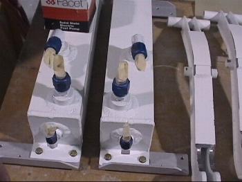
The photos above show the configuration of the header tanks.
These tanks mount on the aft side of the 146 bulkhead, one on
each side of the fuselage.
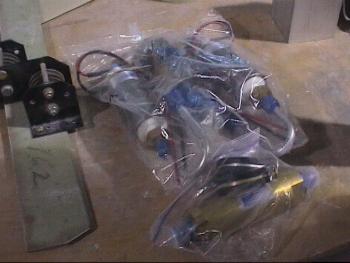
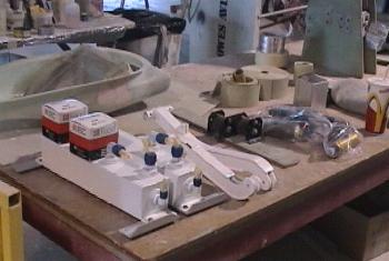
The photo above shows the dual fuel pump arrangement
described in the text above.
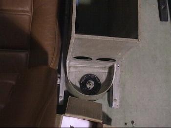
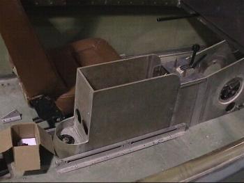
The photos above and below show the location
of the Andair selector valve near the pilot's
seat in Dick Wolf's Seawind.
The following update was added by Mike Bowes in post #917 on October 20,
2003:
Boy is my face red! I mean crimson. The ranting and raving I've been doing
about how this valve will not pass fuel from one side to the other when selected
to "BOTH". Not correct, sorry to say.
Guys, I am so sorry, this was the impression I had formed from observing my
own airplane over the past 18 months. I guess Seawind N369JB has been parked consistently
on flatter ground than I realized.
We had a lively debate in the shop today, concerning what built-in design
features the valve must incorporate so as not to allow transfer of avgas from a
high tank over to the low tank when selected to "BOTH". The final consensus
was there must be built-in check valves...it was the only thing we could imagine
that could produce this effect. Wrong!
I called merry old England and talked to Andy Phillips, at Andair, directly,
late in his day over there. After explaining the nature of our debate, he
laughed and, like a true diplomat, said we could all be right. The valve will
not pass fuel from one side to the other only if it is selected to any other
position but "BOTH". Unfortunately, he explained, it will in fact pass
fuel from high to low if left in the "BOTH" position and parked on
uneven ground, or when left sitting in the water with one wing low.
Therefore, I very much stand corrected and you just may want to install those
big red check valves after all. Especially if you know you can't remember to
move the valve position out of "BOTH" as you exit the airplane at the
end of the day.
Myself, I will not install them at this point. I have found the system
entirely adequate and much to my liking over the past 180 hours. Mike, humble
pie eater, N369JB

The following photo and text was added April 24, 2004: Mike
Bowes has sent us the photo at the lower right showing ISPA member Dick
Wolf's dual fuel pump installation. One of Mike's dual header tanks can be
seen along the left side of the photo.
 Mike also
provides the following text: "As always, a picture is worth a few hundred
words, and this view of the Airflow Performance dual fuel pump and filter
installation in a seawind is pretty much self-explanatory. The location is right
side of the tail-cone with the right side of the photo being direction aft.
Mike also
provides the following text: "As always, a picture is worth a few hundred
words, and this view of the Airflow Performance dual fuel pump and filter
installation in a seawind is pretty much self-explanatory. The location is right
side of the tail-cone with the right side of the photo being direction aft.
The incoming fuel line (coming from the Andair selector valve) rises up from
under floor in lower left of photo. The outgoing, 25 psi line (going to the
engine) is in the upper right corner. Incoming fuel hits the cleanable filter
first, a good thing, and then on to the pumps. Fuel regulator bypass pressure is
routed back to the incoming line ahead of the filter by means of a "T"
fitting inserted in the vertical incoming line. Note there is a reducer bushing
that changes the 3/8" pressure bypass line to 1/2" tubing immediately
before the "T".
This is an example of one man's solution to the installation challenge. By all
means, if you can improve on this, do so. It's a neat, compact, installation
using sweeping curves of tubing and thereby eliminating a great number of
additional fittings which might otherwise have been used. All components are
easily visible and accessible for leak-checking and service, from time to time.
Right site, left side of tail-cone doesn't really matter. You choose where you
want to put it.
Hope this helps those of you who have decided to build in this equipment."
Mike, chief fuel plumbing guy, N369JB